FD3
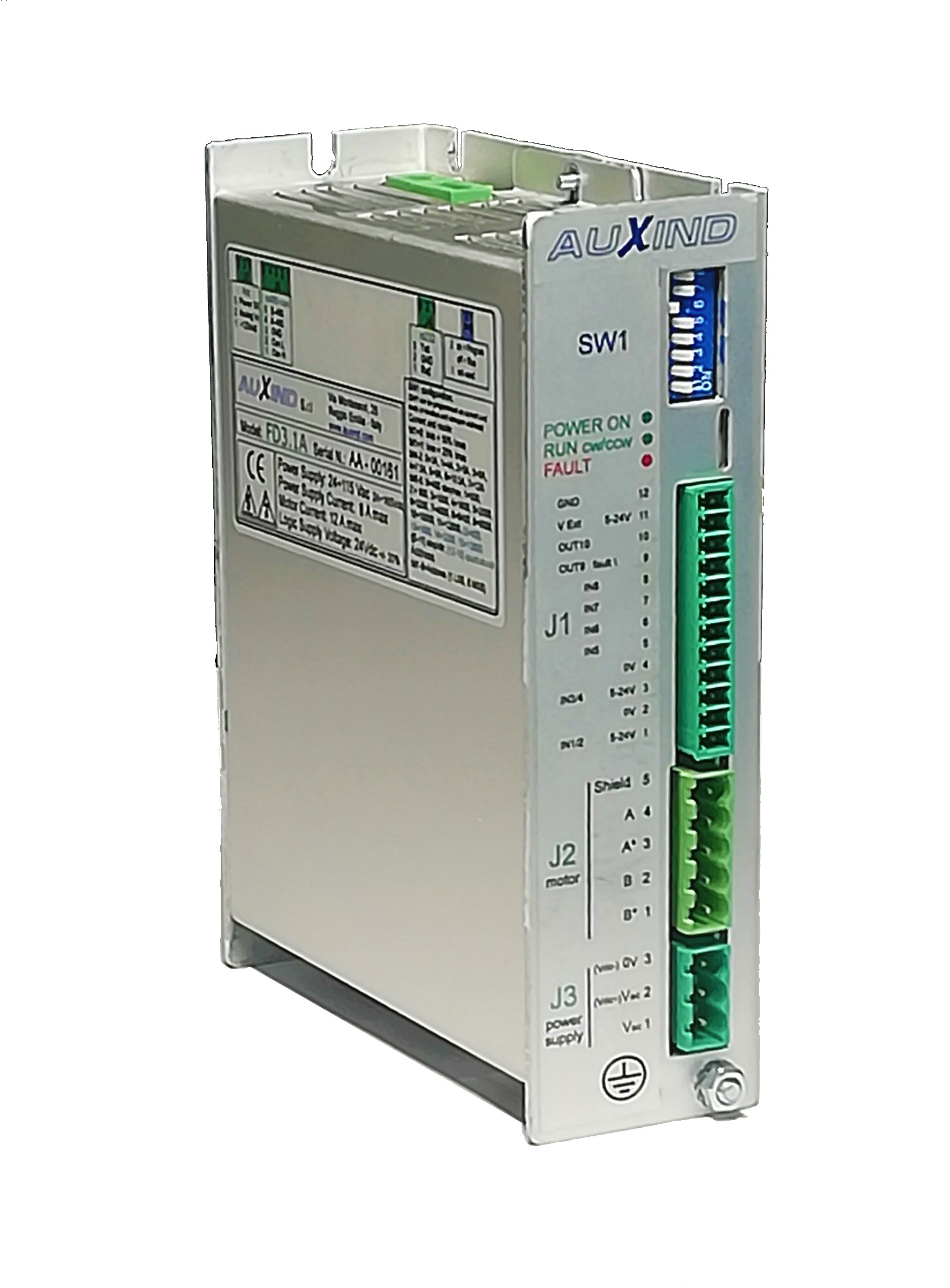
FD3.1 driver shown in the picture
Main characteristics
| Power supply | 24 – 115 VAC or 30 – 165 VDC |
| Motor current | up to 12 APk |
| Dimensions | 150 x 99 x 44 mm |
| I/O | 6 opto-insulated digital inputs, 2 digital outputs 1 analog input |
| Interfaces | Modbus RTU over RS-232 and RS-485 CANopen DSP402 |
| IP | 20 |
| Ambient temperature | 5 – 45 °C |
Features
- Dual H bridge, bipolar chopper, 40 kHz PWM
- AC and DC power supply
- DIP switch to configure motor current and resolution (step/rev)
- Auxiliary power supply for micro-processor and field buses
- Step/dir and quadrature steps inputs
- Start/stop, cycle/sequence selection
- CANopen DSP402 and Modbus RTU
- Firmware and parameters programming over field-bus
- Relays to act as electric brake when powered off.
Description
FD3 belongs to Full Digital family drives, to be installed in an electric cabinet.
FD3 is equipped with configurable I/O’s:
- 2 differential inputs that can be set up as step, direction, quadrature steps, start, stop, etc.,
- 4 single ended inputs that can be configured as homing and limit switches, cycle and sequence selection, enable, disable current, etc.
- 2 outputs that can be configured as alarm, running, etc.
Using DIP switches located on the front panel it is possible to set up motor current and resolution (steps/revolution) or the node address on the field-bus.
The drive can be controlled and monitored through RS-232 (from 4 800 to 115 200 bps) and opto-insulated RS-485 (from 4 800 to 921 600 bps) over Modbus RTU protocol.
Suffix A identifies the model equipped with transceiver CAN opto-insulated (es. FD3.1A) to communicate over CANopen protocol (from 10 kHz to 1 MHz).
Suffix D identifies the model equipped with insulated DC/DC, used to keep the logic supplied also in case of loss of main power supply. This allows to maintain encoder position counting and field bus communication alive.
Suffix R identifies the model equipped with relays to act as electric brake in case of loss of power.
Ordering codes:
| Model | digital I/O | RS-232 | RS-485 | IN analog | CANopen |
|---|---|---|---|---|---|
| FD3.1 | ✓ | ✓ | ✓ | ✓ | Suffix “A” |
| FD3.2 | ✓ | Suffix “S” | Suffix “B” |
Other suffixes:
D = DC/DC
R = relays
E = feedback for incremental encoder inputs
G = DIN rail hook
C = IN5 enable current